4S-192S 200A Smart YL DIY BMS LiFePO4 Li-ion LTO With Relay Bluetooth-Compatible APP Monitor Solar Power LCD Display
You will be redirected to AliExpress to complete your purchase
Specifications
- Brand Name
- RJXZS
- Origin
- Mainland China
- High-concerned chemical
- None
- Condition
- New
- Type
- Voltage Regulator
- Supply Voltage
- 300V
- Package
- SOP
Product Description
Notices:
1.If you have no experience for DIY battery assembly, please spend more time to check more details or ask us before you buy.
2.The BMS are with much components and software, Please do well in insulation for each step. Otherwise, it will dameged the
whole pack.
3.The BMS is suitable for 4S To 192SLi-ion/LiFePO4/LTO Battery Pack.
4.Packing list is with two relays.
5.Current is continuous current.
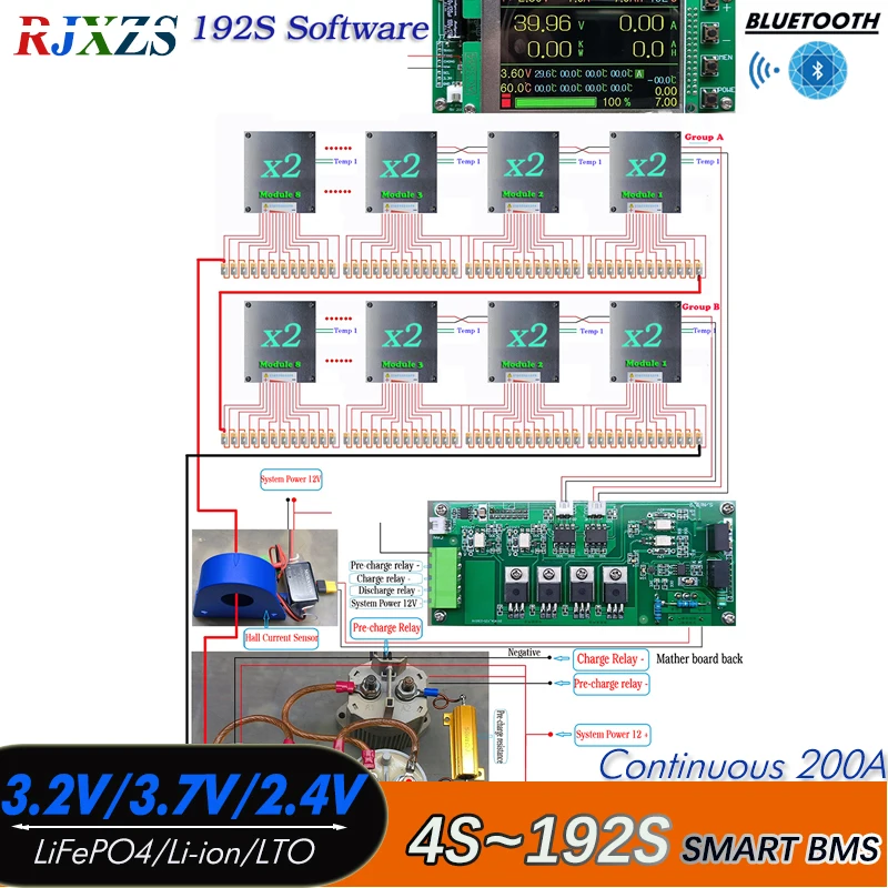
1. Real time monitoring of 4-192 series single unit voltage , Accumulated total voltage is within 1000V. Single module management is a maximum of 12 strings and a minimum of 4 strings(Due to the fact that the power supply for module operation is taken from the battery, the total voltage of a single module must not be less than 9V. Any excess unused channels must be connected to the positive pole of the highest battery in a single module),the total input voltage of a single module shall not exceed 75V, the monitoring voltage range of a single section shall be 0-5V, and the total input voltage of the host shall not exceed 60V;
2. Real time monitoring of total voltage, charging and discharging current, power, temperature, and statistics of actual charging and discharging ampere hours, and display with a graphical progress bar. Each module is equipped with 1 temperature detection channel;
3. The system has functions such as single overcharge protection, single over discharge protection, over current protection, high temperature protection, low temperature protection, differential pressure protection, and battery failure protection;
4. The host is equipped with various running lights to indicate the system running status without using the screen;
5. 3.5 inch IPS color screen display, ultra wide viewing angle, and clear working status at a glance;
6. Supports three ranges of Hall current sensors, with a default standard range of up to 400A. It has a manual calibration function for Hall current sensors, a self calibration function for the collection module, and a total measurement error of 1.2MV for individual voltage collection;
7. There are two types of relay schemes: same port and split port, with different control software. The interface type needs to be determined before procurement;
8. The acquisition module adopts a two way cascading structure, each of which can connect 1 to 8 arbitrary number of acquisition modules. The host automatically
recognizes the number of acquisition modules, and the two way acquisition modules support a total of 16. The acquisition module is connected with two core CAT5 twisted pairs, with a length of up to 40 meters;
9. The power outage module of the host will enter a sleep state while releasing all relays. The power consumption of the module is only 4UA, which will not cause the loss of battery power;
10. The module has an automatic battery balancing function, which balances the voltage drop of the battery and stops when the drop is 0.001V. The balanced discharge current is 200MA;
11. The system is designed with full isolation, and the collection modules are isolated from the host. All interfaces can be hot swapped, and temperature sensors, display screens, and Bluetooth external devices that are not used can not be installed;
12. Actively dissipate heat and heat, automatically start the fan when the temperature reaches the set value, and automatically start PTC heating when the temperature drops below the set value;
13. Supports RS232 TTL communication and CAN communication, with an Android mobile app that monitors and controls the status and parameter settings of the host through Bluetooth. The app has the ability to query protection history records and can query the last protection record;
14. The same port connection method automatically controls the charging and discharging relay. In the split port connection method, the charging and discharging relay is automatically restored according to the charging and discharging recovery set value. When there is over current protection, over temperature protection, battery string error, low temperature protection, and differential pressure protection, which are related to safety, the charging and discharging relay is closed at the same time. At this time, the channel must be manually opened;
MCU POWER
MCU power is DC: 8V to 60V
Recommend use 12V. red wire is positive, black wire is negative.
Current Sensor ( hall sensor)
Recommend input use 12V. (red is positive, black is negative. )
Input: DC: 9V to 36V
Output: ±12V DC/416mA
VAM (Voltage acquisition module)
Each module Support 4S to 12S, The minimum is 4S, the maximum is 12S,less 12S, short high bit signal.
With communication port, with temperature sensor port.
Relay is EV200AAANA
Coil voltage is : 12V to 24V, Recommend use 12V.
Bluetooth App
Only support Andriod
After receiving the BMS, please do not hurry to link the battery, please remove the motherboard screws, check inside of the port name carefully.
1.The distribution of small key switches and joints welding.
2.Then reassemble the motherboard. Do not connect the battery in the case of the motherboard decomposition, so that the permanent damage the motherboard
3.The following figure is to test board to connect the battery the most simple wiring diagram.
4.Motherboard power supply voltage: 24V ~ 100V (many customers can not start the motherboard, because the motherboard input voltage is too low)
5.Start the motherboard: it needs to link the line completely, hold down the small switch for 3 seconds, until the motherboard red light, release the switch.
6.About Turn ON/OFF Button:
A, Hold down the boot switch for about 5 seconds, release the switch, the motherboard display light goes out;
B, the phone APP link motherboard, click APP on the button to close the motherboard.
7.If the motherboard start successfully, please disconnect the power supply. Put balance line into the motherboard, the display can be displayed the battery voltage. The battery equalizer line must be checked to see if the connection is correct.
Pros & Cons
Pros
- Supports three common battery chemistries for broad project compatibility
- Includes both Bluetooth APP and LCD monitoring for easy status tracking
- 200A high current rating suitable for large-scale solar and battery projects
- New, unused condition ready for DIY integration
Cons
- Requires careful insulation during installation, which is challenging for novice DIYers
- Only compatible with 4S battery configurations, limiting flexible use
- No official warranty coverage is advertised
- Minimal SOP packaging without included mounting hardware or guides
Common Questions
What battery chemistries and cell counts is this BMS compatible with?
It supports LiFePO4, Li-ion, and LTO battery packs, specifically designed for 4S configurations as noted in the product title.
What real-time monitoring features does this BMS include?
It has a Bluetooth-compatible APP monitor and an integrated LCD display to track battery pack status and performance.
What installation precautions are required for this BMS?
The BMS has many components and requires proper insulation during assembly to avoid damaging the unit or connected battery packs.
What is the maximum continuous current rating of this BMS?
It has a 200A continuous current rating as listed in the product title.
Where is this BMS manufactured and what packaging does it arrive in?
It originates from Mainland China and is packaged in an SOP package per the product specifications.
Product information last updated on November 18, 2025